Research · Michigan Tech
Balancing Bike
A 4 kg bike that holds itself upright with two ducted propellers. Published in international Robotics journal with me as first author, three months after I proposed it on my second day in the lab.
A Self-Balancing Tandem-Wheel Mobile Robotic System Using Differential Propeller Thrust for Active Roll Stabilization
Bike Testing
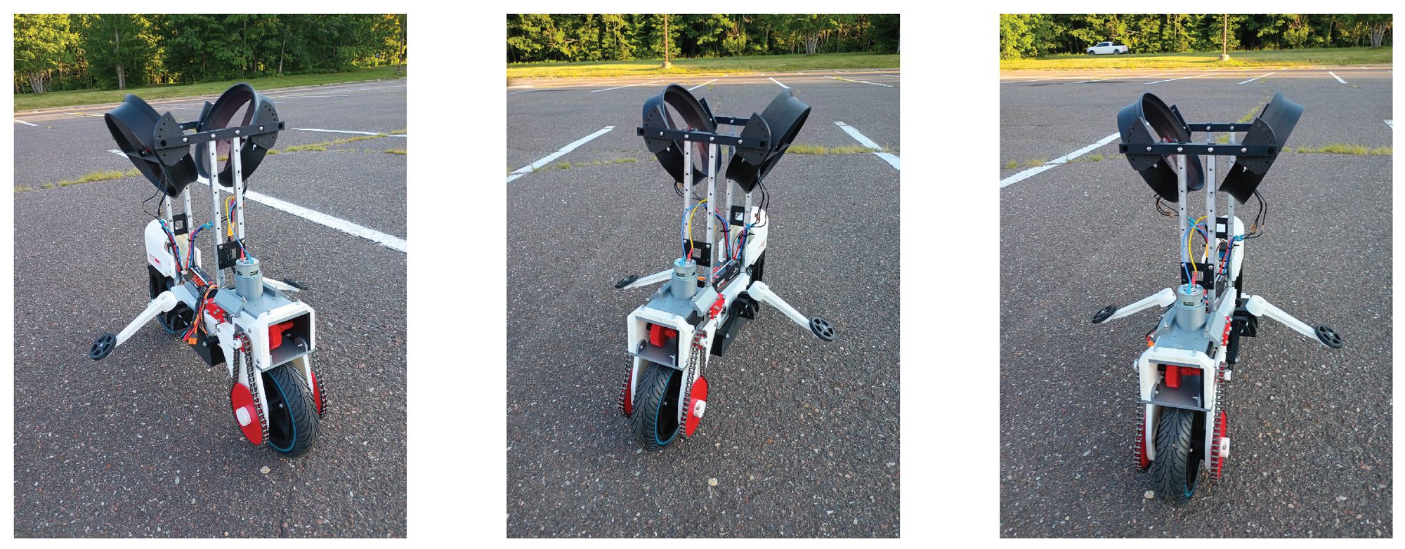
Fully assembled bike balancing on its own.
The proposal
Professor Choi and graduate student Samuel Mbadiwe were weighing which application of a self-balancing bike would be worth a paper. On my second day I suggested a different mechanism: a duct on each side of the bike with a propeller inside, using thrust to hold it upright. We went through the self-balancing research and didn't find anyone who'd tried it yet. The next month was spent working around this idea.
First thrust test
The propellers' first run. The bike proved to be strong enough by almost flying out of my hands.
My task: to design the whole physical bike
Professor Choi instructed me to design the whole bike from scratch, including the steering system, motorized drivetrain, the ducts and propellers, and the electronics board. Thankfully with Samuel's help, I was able to grind multiple prototypes out using the Bambu Lab X1E and fusion360 as my main software for CAD.
Two duct designs
The first duct was a plain cylinder with a hole in it. After reading about rocket nozzles I reshaped it to draw in air and push it out more efficiently, which is the version we ended up with in the paper. A manual adjuster sets each duct's tilt, aiming part of the thrust sideways to add to the roll correction.
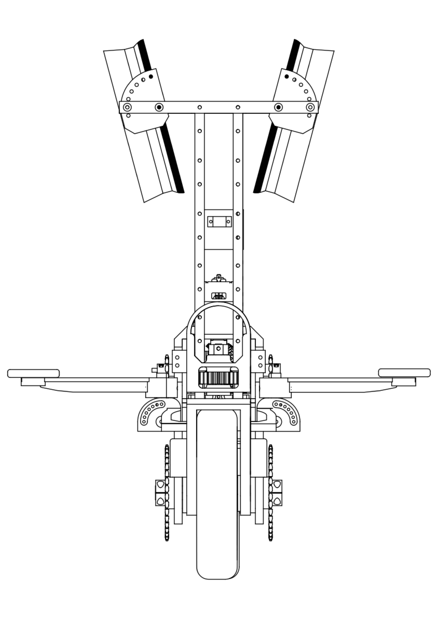
CAD timelapse
Thirty seconds of the assembly coming together in Fusion 360. I built out the model over two months.
Drivetrain and steering
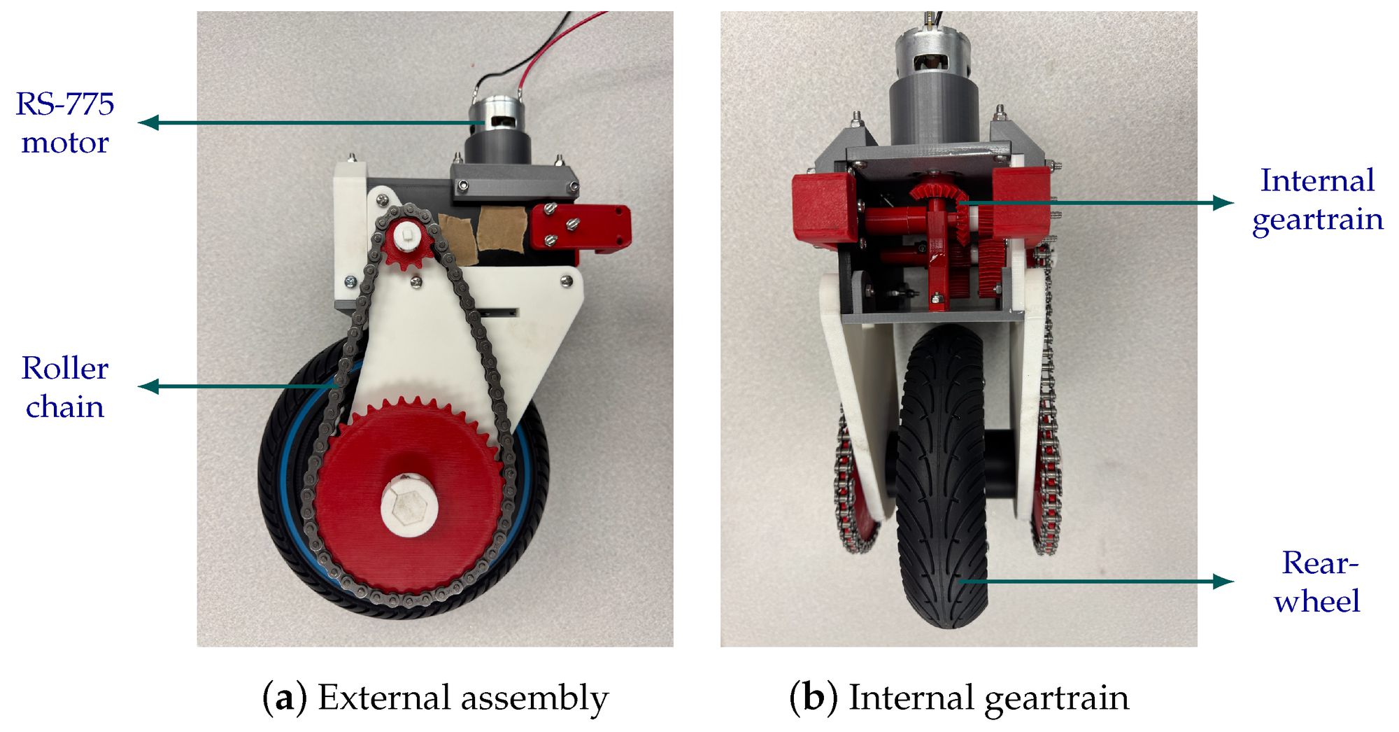
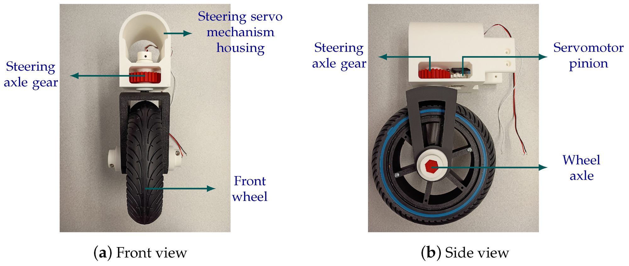
I decided to have a RS-775 motor drive the rear wheel through a roller chain and a 3D-printed geartrain with an 11.2:1 reduction. Up front, a DS3225 servo steers the wheel through its own gears.
Learning the electronics
I learned alongside Professor Choi and Samuel the whole time. I soldered much of the wiring, plus the Arduino's mini breadboard PCB and its hubs and ports. Professor Choi also gave me a short lecture for fun on semiconductors that tied back to my chemistry class. I learned about silicon's four valence electrons and how merging it with an element that has three valence electrons, like boron, has holes; merge it with an element that has five, like phosphorus, and you get a spare electron. Where the two kinds meet, the junction sets up an electric field, and that field is what lets a diode or transistor control current.
Remote work
I flew out of Michigan in July but kept communicating with my team over the summer via WhatsApp and Zoom. I sent new CAD iterations, Samuel printed and tested them, we changed code together in VS Code and Arduino IDE, and we wrote out the paper in Overleaf alongside the hardware.
Coding issue
The propellers could not reach the speed the Arduino asked for in time. By the time a motor spun up, the bike had already leaned further. We fixed it with prediction: the bike stores the motor speed each approaching lean angle needs and commands it a few milliseconds early, so the thrust arrives when the lean does.
Holding itself up
The roll loop closing on lean angle.
Writing the paper
This was my first academic paper. Because I designed the bike, Professor Choi asked me to write the mechanical section: the ducts, the steering, the motorised drive, and the electronics board. Samuel guided me on how to describe a design process in a form reviewers accept. I supported Samuel and Professor Choi on the electronics and coding section, and they gave me feedback on the mechanical portion.
I had never touched LaTeX before this, but I now use it for multivariable calculus and physics.
Result
After three months we had a 3D-printed self-balancing bike that drives on rough terrain, holds itself upright at a standstill, recovers from leans up to 15°, and drives for an hour on a battery!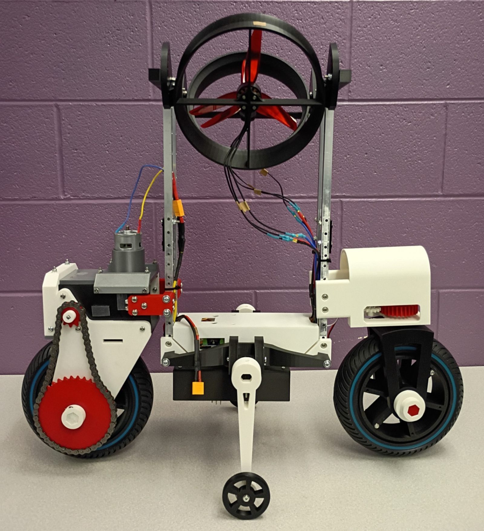
Read the whole paper
Thank you Professor Choi and Samuel for an amazing experience :)